Note: This method requires roughed in electrical prior to installation which must be centered 33.5” from the floor to comply with ADA requirements. We recommend that a licensed electrician installs Swift UV. Please adhere to all local and national building codes when installing the wall installation power cable.
Step 1: Use the supplied template to mark out where you will need to install your roughed in electrical box and mounting hardware on the wall for proper installation.
Step 2: Use proper wall anchors or ensure proper depth screws are used when mounting into wall studs. Note: Wall-mounting hardware not included.
Step 3: Carefully hang the Swift UV on the two upper screws taking care to align them with the two mounting points on the back of the Swift UV (Figure 01.)
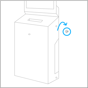
Figure 01.
Step 4: Loosen the two recessed screws on the right side of the Swift UV main housing with the provided Phillips screwdriver and rotate the main housing open (Figure 02).
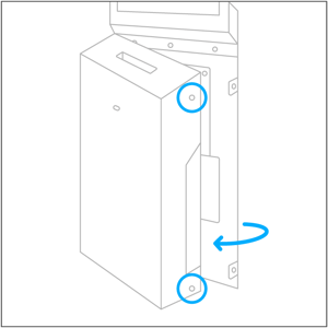
Figure 02.
Step 5: Install the lower right screw and tighten the two upper screws (Figure 03.).
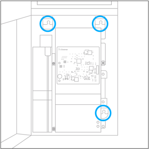
Figure 03.
Step 6: Loosen the two thumbscrews on the right side of the disinfection chamber. Rotate the fan duct out (Figure 04.) then rotate the disinfection chamber out to gain access to the back panel (Figure 05.).
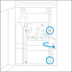
Figure 04.
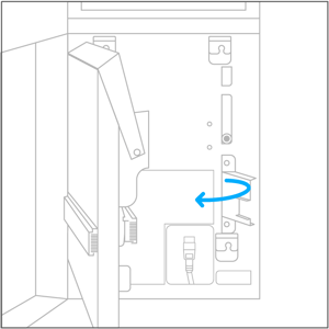
Figure 05.
Step 7: Install and tighten the final screw in the lower left corner in accordance with the anchors being used (Figure 06.).
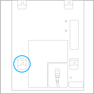
Figure 06.
Step 8: Connect the power cord whip to the rough electrical within the junction box and store any excess cabling in the junction box (Figure 07.).
Brown lead to line voltage (usually black in color)
Blue lead to neutral wire (usually white in color)
Green/yellow lead to the ground wire (usually bare copper or green in color)
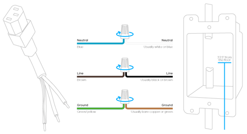
Figure 07.
Step 9: Plug the power cable into the power supply terminal on the Swift UV (Figure 08.).
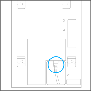
Figure 08.
Step 10: Rotate the disinfection chamber and fan duct back into position and secure the two thumb screws on the right side.
Step 11: Turn the power switch to the "ON" position (I) (Figure 09.).
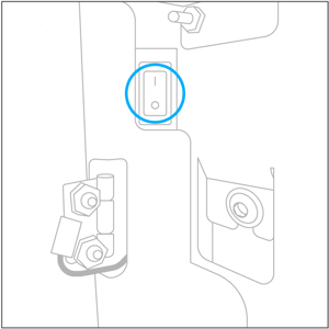
Figure 09.
Step 12: Close the main housing of the Swift UV and re-tighten the two Phillips screws.